
Programmable Logic Controllers Explained
Programmable logic controllers (PLCs) were invented, to control, safety and sequencing of automated equipment used in the auto industry was mostly made up of a large number of relays, drum sequencers, cam timers and closed loop controllers. Updating these functions for the annual model change-over meant electricians had to rewire each relay individually to change the operations. This was extremely time consuming and expensive.

Programmable logic controllers changed all that. The PLC is a computer control system that continuously monitors the status of input devices and makes adjustments based on the custom program installed to control the state of output devices.
Just about every production line, machine operation or process can be enhanced with this type of control system. One of the biggest advantages of this system is that operations can easily be changed or replicated while vital information is collected and communicated.
Another big advantage is that the PLC system is modular. This means companies can mix and match different Input and Output devices to create an application that best suits their needs.
History of Programmable Logic Controllers
In 1968, GM began looking for a better system to control the industrial process. The computers they were using required specialized programmers, and a stringent operating environment that included temperature control, cleanliness and a reliable power supply. What they wanted was something less complicated. Bedford Associates was chosen to develop this new system.
The company created a new company dedicated to this project: Modicon, which stood for Modular Digital Controller. Modicon would develop, manufacture, sell and service this new product. Dick Morley was one the leaders of this project, and is now considered the “father” of PLCs. The first model was produced in 1969, called the 084. In 1973, Michael Greenberg improved the design of the original, which was called the 184. The 184 quickly became a commercial success.
The PLC Modican Developed:

Eliminated the need to rewire the system and add additional hardware for each new logical configuration.
Dramatically increased the functionality of the controls and reduced the cabinet space required to house the logic.
Since the PLC is basically a computer, its main component is the CPU. It contains the program that controls the PLC and tells it how to execute the control instructions. This program is securely stored in a nonvolatile memory system so that it won’t be lost in case of power failure.
The CPU communicates with other devices, including input/output devices, networks, programming devices and other PLC systems. It also performs routine maintenance operations such as internal diagnostics and communications.
The biggest difference between a PLC and a regular computer is that PLCs are built to withstand extreme conditions such as heat, cold, dust and moisture. Plus, they have the capability to handle extensive input/output arrangements.
How the Programmable Logic Controller Work
The programmable logic controller performs four basic operations: Input Scan, Program Scan, Output Scan, and Housekeeping. The operations are performed in a continual loop.

1. Input Scan – Scans all of the input devices connected to the system and reports their state.
2. Program Scan – Executes the program logic created by the user.
3. Output Scan – Activates or deactivates the output devices connected to the system.
4. Housekeeping – Performs a variety of maintenance operations such as communicating with various programming terminals and internal diagnostics.
Ladder Logic is the most commonly used language in programming a PLC, however it isn’t the only one. Other PLC programming languages often used include:
Ladder Diagram (LD) – Based on the traditional ladder logic, which is a graphical programming language, LD expanded the commands to include more functions like timers, counters, math operations and shift registers.
Sequential Function Chart (SFC) – This is a sophisticated method of programming extremely complicated control systems at a high structure level. An SFC program is an overview of the control system. The basic building blocks of the system are complete program files. All of the program files are created by using one of the other programming languages. The approach of the Sequential Function Chart is to break large, complex programming tasks into simpler, easier to manage tasks.
Instruction List (IL) – This is a low level language used as an “assembler.” It is based on lists of commands found in a wide range of PLC systems, including CNC machines.
Structured Text (ST) – This high level text language is based on a more structured programming style, similar to PASCAL. It is capable of a wide range of functions and can support multiple operators.
Function Block Diagram (FBD) – This is a graphical language that depicts signals and the flow of data through function blocks. FBD is a helpful way of visually expressing how the control system algorithms and logic interconnect.
Common Input Devices:
- Switches and push buttons
- Sensing devices –proximity sensors, limit switches, photoelectric sensors
- Condition sensors
- Encoders – pressure switches, temperature switches, level switches, float switches, vacuum switches

Common Output Devices:
- Valves
- Fans
- Motor starters
- Variable frequency drives
- Printers
- Solenoids
- Pumps
- Actuators
- Counters
- Horns and alarms
- Control relays
- Stack lights
What to Consider When Choosing a Programmable Logic Controller

With all of the PLC systems on the market, it may be difficult to decide which one is best suited for your needs. Aside from the cost, other things you may want to consider include:
- Where will the system be used?
- Will it be set up in one spot or spread out across the company?
- Does the PLC have the required amount if memory to run your programs?
- Does the system need to be connected to a network? If so, can this be added to the PLC?
- Is the system fast enough to meet the requirements of your application?
- How will you communicate with the programmable logic controller?
- What software do you need to operate and program the unit?
- Is the PLC capable of managing all of the input and output devices required by your application?
There may be other concerns and considerations specific to your applications. Research the various systems to make sure you choose the one that meets your unique needs.

Recent Articles
-
Electrician Information Resource | How to Become an Electrician & More
Jun 18, 22 02:30 PM
 At Electrician Information Resource you will learn about how to become an electrician, topics covered in electrician trade school, & so much more!
 -
Electrician Training in Montana | Earn Big By Becoming an Electrician
Oct 13, 20 11:08 AM
 Comprehensive guide to electrician training in Montana, types of licenses, job market, wages and career opportunities available for aspiring electricians.
 -
Basic Electrical Theory: Understanding Electricity
Sep 17, 20 10:27 AM
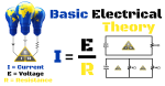 Electrician Information Resource explains basic electrical theory. Learn the basics of what electricity is, and how it works.