
Basic Electrical Theory: Understanding Electricity

Even though basic electrical theory was not understood until much later, electricity has existed in the world since the beginning of time.
Long before anyone heard the word electricity, people had seen lightning and experienced shocks from electric fish. Written work from the Ancient Egyptians dating back to 2750 BC mentioned a type of fish they called “Thunderer of the Nile”. They believed these fish were to “protect” all of the other fish.
Ancient writings from Pliny the Elder and other naturalists described a numbing effect when shocked by a catfish or a torpedo ray, and realized such a shock could travel along a conductive object.
However, electricity remained mostly a strange phenomenon until 1600, when the English scientist William Gilbert began to study electricity more closely.
Many other scientists, inventors and experimenters became fascinated with electricity and began their own research, which led to our understanding of electricity today.
Basic Electrical Theory: Electric Charge
Every piece of matter is made up of molecules and all molecules are made up of atoms, which are made of protons, electrons, and neutrons.
The negative charge is carried by electrons, while the positive charge is carried by the protons, and neutrons are naturally neutral. The number of protons in an atom does not change because they are locked in the nucleus.
Electrons orbit the nucleus, and therefore can be lost or gained. The charge of one electron will counteract the charge of one proton, and atoms tend to prefer to stay at a balanced charge. When an atom has too many electrons, it will want to release those electrons to something with a weaker charge. When something has an electric charge, it means that there is an imbalance of electrons, either too many or too few.
When we measure the difference in electric charge between two points, it is known as voltage. Typically, the earth is used as a common reference point, so when a circuit has 120 Volts, that is the difference between the source voltage and the ground’s voltage.
An example of this is often seen when someone is working without wearing properly insulated footwear. If the worker comes in contact with something that is electrically charged, like an exposed wire or the terminal on a battery, they will experience an electrical shock because the body offers a path to ground with less resistance than the surrounding air. This means the body has become part of the circuit.
Basic Electrical Theory: Electric Current

When a conductive path is provided for excess electric charge to take, the electric charge moves and creates an electric current. The amount of current is based on the supply voltage and the resistance in the circuit. Current is measure in units of Amperes, or Amps for short, and is equal to one Coulomb (the amount of charge that 6.242×10¹⁸ electrons have) per second. The current will prefer to take the path with the lowest resistance.
Basic Electrical Theory: Electrical Resistance
How much opposition the conductor or metal wire presents to the electric current flow is the electrical resistance. The lower the resistance, the easier current will flow. Think of current like water flowing through a pipe, if the pipe is small there is more resistance to water flow, if the pipe is large the water will flow much easier. A larger wire size has less resistance and will allow more current to flow. Electrical resistance is measured in units of Ohms. Resistance is also affected by the material itself. Most metals are good conductors, which means they have low resistance, because their electrons can be gained and lost very easily. Insulators, like plastic or wood, have electrons which are much more tightly bound to the nucleus, which means that they are harder to move around. Also, as a material heats up, its resistance increases, and the resistance decreases as it cools down.
Ohm's Law
Ohm’s Law is the fundamental equation for electricity and governs the vast majority of electrical work that we do.
It was named after Georg Ohm, a German physicist who published a treatise in 1827.
In it, he explained measurements of applied voltage and current by using a simple electrical circuit made with varying lengths of wire.
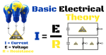
The law states that electrical current in a circuit or conductor will always be proportionate to the voltage across the conductor or circuit, and inversely proportional to the total resistance.

V (voltage) = I (current) x R (resistance)
Let’s do an example calculation; we are installing a 120V light bulb with a resistance of 100Ω (Ohms). If we move the formula around, we find that:
I=/V/R
So, 120V / 100Ω= 1.2A
Circuit Basics
There are two basic ways in which resistive devices can be hooked up, series and parallel. Loads connected in series form a continuous loop and provide only one path for the current to travel. All of the current in the circuit has to travel through each part of a series circuit. When resistors are connected this way, their resistances add together and increase the total circuit resistance. Looking back at Ohm’s Law (V/R=I), we can see that if the voltage is constant and the resistance increases, the current in the circuit will actually decrease. However, if you were to wire a string of lights in series, each light in the loop would be dimmer than the last, and all the lights would dim as you added more lights. Because of this, most electrical circuits are wired in parallel.
Parallel wiring simply means that there are multiple paths for the current to travel. Typically, each resistive device will have its own direct path to the voltage source. As you add more devices in parallel, the total circuit resistance goes down and the current increases. We can determine the circuit resistance with the formula:
1/R(total) = 1/R(first device) + 1/R(second device) + 1/R(third device) …
It may seem a little complicated, but just remember that as you add more devices in parallel, the resistance decreases and the current increases.
Basic Electrical Theory: Electric Circuit
An electric circuit provides a path for the current to flow to a from a point. The electric current always flows from positive to negative, and takes the path with the least resistance.
An example of this is often seen when someone is working without wearing properly insulated footwear. The worker will experience an electrical shock, because the body offers a path towards the ground with very low resistance.
This means the body has become part of the circuit.
Faraday's Law and Electromotive Force
The e.m.f. (electromotive force) is voltage generated by a source of energy, or by varying the magnetic field, as discovered by Faraday.
Faraday’s Law was developed when he showed that a conductor placed within a magnetic field with time variations, electric current would be induced.
The name – electromotive force – implies this is a force, when in fact the e.m.f. is the energy or potential per unit of charge. This potential is measured in volts.
What is a Transistor?
A transistor is mainly used as either an amplifier or a switch. The transistor is made of semiconductor material, and is an important part of the circuit.
The device has three terminals (base, collector and emitter), one of which is used to turn the transistor ON or OFF. Inside there are two junctions of semiconductors.
Beyond the Basics: Further Reading
These are the electrical quantities used to describe basic electrical theory. You will find them in all electrical systems.
Some systems may be more complicated and complex, while others might be very simple, but every one will contain these quantities.

Recent Articles
-
Electrician Information Resource | How to Become an Electrician & More
Jun 18, 22 02:30 PM
 At Electrician Information Resource you will learn about how to become an electrician, topics covered in electrician trade school, & so much more!
 -
Electrician Training in Montana | Earn Big By Becoming an Electrician
Oct 13, 20 11:08 AM
 Comprehensive guide to electrician training in Montana, types of licenses, job market, wages and career opportunities available for aspiring electricians.
 -
Basic Electrical Theory: Understanding Electricity
Sep 17, 20 10:27 AM
 Electrician Information Resource explains basic electrical theory. Learn the basics of what electricity is, and how it works.