
Series vs Parallel Circuit - Understand The Differences Between The Two

What are series and parallel circuits? How are they different from one another, and can you use them in combination?
Circuits with just one resistive load and one battery can be analyzed quite simply, but are not usually found in practice.
More commonly, you will see circuits where two or more components are connected together. These circuits will be connected in either series, parallel or a series parallel combination.
A Series Circuit:

In this example there are three resistors (R1, R2, and R3 – the numbers are for identification only and do not represent the value in ohms).
They are connected from one battery terminal to the other. The main characteristic defining a series circuit is that current is constant throughout circuit and will flow along just one path. If this path is broken at any point throughout the circuit current will not flow.
This circuit shows current, using electron theory, flowing counter-clockwise, from point 4 through to 1 and back around to 4. Using conventional theory current would flow in a clockwise direction, from positive to negative.
A Parallel Circuit:

There are still three resistors in this example, but this time the electrons have more than one path where they can flow continuously. The one from 8 to 7 to 2 to 1 and back to 8.
One from 8 to 7 to 6 to 3 to 2 to 1 and back to 8. And the one from 8 to 7 to 6 to 5 to 4 to 3 to 2 to 1 and back to 8. Each of the paths (through R1, R2, and R3) are called branches.
A parallel circuit is when all components are connected in between common electrical points. Note that points 1, 2, 3, and 4 are all electrically common. As are points 8, 7, 6, and 5. The battery and all of the resistors are connected between these points.
In this parallel circuit if one resistor is burnt out it will not affect the rest of the circuit.
In many cases you will see a combination series and parallel circuit:

This example combination series and parallel circuit shows two loops where the electrons travel – one from 6 to 5 to 2 to 1 and back to 6, and the other from 6 to 5 to 4 to 3 to 2 to 1 and back to 6.
Note how the path of both currents pass through R1 (from point 2 to point 1). This means that R2 and R3 form a parallel, while R1 forms a series with the R2-R3 parallel combination, to create a series and parallel circuit.
Understanding Circuits
This is an essential part of electrician math. Let’s begin with a series circuit that consists of one battery and three resistors.
The first principle you will learn is that in a series circuit the current remains the same through every component. This is because the electrons can only flow along one path, and the rate of flow must remain equal.
In this arrangement the electrons are flowing counter-clockwise. There is one voltage source and three resistances. How would you use Ohm’s Law in this situation?
The main rule of Ohm’s Law states that all elements (current, voltage, power and resistance) must be relevant to each other in terms of the same two points in a circuit.
This means that in a circuit with one battery and one resistor, you can calculate any of the elements because they can all apply to the same two points in the circuit:
 |
 |
Here you have points 1 and 2 connected with a wire presenting only minor resistance, as do points 3 and 4. Points 1 and 2 are electrically common, and points 3 and 4 are also electrically common.
Since you know that across the battery you have an electromotive force of 9 volts between points 1 and 4, and since points 2 and 1 are common and points 3 and 4 are common, you must also have 9 volts across the resistor between points 2 and 3.
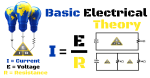
Therefore, you can apply Ohm’s Law (I = E/R) to the current flowing through the resistor, because you know how much voltage (E) there is across the resistor and how much resistance (R) the resistor presents.
Since all of the terms (E, I, R) apply to the resistor (the same two points in the circuit), you can use the Ohm’s Law formula.
Now, when you have circuits with more than one resistor, you have to be careful in applying Ohm’s Law to a series and parallel circuit.
Below, you have a three-resistor circuit. You know that there are 9 volts between points 1 and 4. However, you can not just take the 9 volts and divide it by 3k, 10k or 5k Ω in order to find a value for the current, because you don’t know the individual voltage across the resistors.

In this figure, the total is 9 volts, whereas 3k, 10k, and 5k Ω are the quantities for the individual resistors. If you plugged in a number for total voltage into an Ohm’s Law equation with a number for individual resistance, you would not get an accurate result for any quantity in the actual circuit.
For R2, Ohm’s Law will relate the amount of voltage across R2 with the current through R2, given the resistance of R2 at 10kΩ.
But, because you don’t know how much voltage there is across R2 (you only know the total voltage the battery supplies across the combined resistors) and you don’t know the amount of current through R2, in this case, you would add the resistors directly to get the total resistance, and then apply Ohm’s Law.
The same is true for the others as well. You can only use the equations of Ohm’s Law when all terms represent their respective quantities between the same two points in the circuit.
This applies to both series and parallel circuit configurations.

Recent Articles
-
Electrician Information Resource | How to Become an Electrician & More
Jun 18, 22 02:30 PM
 At Electrician Information Resource you will learn about how to become an electrician, topics covered in electrician trade school, & so much more!
 -
Electrician Training in Montana | Earn Big By Becoming an Electrician
Oct 13, 20 11:08 AM
 Comprehensive guide to electrician training in Montana, types of licenses, job market, wages and career opportunities available for aspiring electricians.
 -
Basic Electrical Theory: Understanding Electricity
Sep 17, 20 10:27 AM
 Electrician Information Resource explains basic electrical theory. Learn the basics of what electricity is, and how it works.